")
")
1. FAQ: Overview and Setup of the Methane-Plasmalysis (Plasma-Pyrolysis)
Hydrogen is an important component of industrial decarbonization. Graforce's methane plasma pyrolysis (Plasmalysis) is an innovative technology that efficiently converts methane into hydrogen and solid carbon. This technology is characterized by an impressive methane conversion rate of 98 % with energy costs of only 10.7 kWh per kg of hydrogen and waste heat utilization of 25 % to 30 %. Another advantage is the generation of CO2-free high-temperature process heat of up to 750 °C, which can be reused in industrial processes, and the production of syngas from biogas or captured CO2 with low upstream emissions.
The environmental compatibility of this process is particularly noteworthy, as it does not cause any direct CO2 emissions. Instead, solid carbon is produced, which can be used in various industries such as steel and concrete production, significantly improving the LCOH and CO2 balance.
The innovative approach of Methane-Plasmalysis enables a further reduction in the ecological footprint through the use of waste heat and solid carbon. Graforce aims to tap into the market for steel, concrete, refineries, and self-sufficient district heating. The business model is based on licensing in regional markets, which facilitates scalability and adaptation to local market requirements.
The technology was first introduced in pilot plants at a MOA hotel in Berlin, an HCNG filling station in Berlin, and a 0.5 MW plant (with three 167 kW modules) at a refinery (RAG Austria AG) in Austria with a capacity of 50 kg of hydrogen per hour. Depending on market demand, scaling up to multi-MW plants is planned.
The capital requirements and operating costs are competitive, with estimated electricity generation costs for low-carbon hydrogen of € 2.60/kg H2 and € 450/t solid carbon in Germany. This cost efficiency, combined with a low carbon footprint, makes methane-Plasmalysis an attractive investment. In addition, the technology offers a high level of safety and environmental compatibility, which strengthens investor confidence in compliance and risk management.
With the potential to achieve significant CO2 savings and potentially generate emission credits, Graforce's methane plasma technology is positioning itself as a leading technology in the production of green/turquoise hydrogen. This underscores Graforce's commitment to providing innovative solutions for a sustainable future and fully exploiting the potential of our technology for decarbonizing steel production.
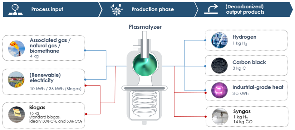
Q 1.1 What does the Plasmalysis do?
Graforce’s system uses a high-efficiency hydrogen DC plasma. Built on patented corona discharge know-how, it can dynamically switch between arc and coronally influenced plasma modes, optimizing performance, energy use, and product quality — all in one flexible platform. Both plasma modes benefit from plasma-catalytic effects — high-energy electrons, radicals, ions, and excited molecules significantly lower the energy barrier for methane dissociation. This enhances reaction efficiency well beyond conventional thermal processes. The result is a methane conversion rate of ~98 %, with hydrogen production requiring only 10.7 kWh per kg of H₂, assuming that 25 % to 30 % of the generated high-temperature waste heat is recovered and utilized — a stark efficiency advantage over water Plasmalysis (50–60 kWh/kg H₂, with no useful solid byproduct).
The reactor can operate in two distinct plasma modes:
- A coronally influenced plasma discharge, which is non-thermal, produces low to moderate plasma densities, and — critically — does not consume the electrodes. This makes it ideal for lower-energy use cases such as surface activation, partial dissociation, or energy-saving modes.
- A high-density hydrogen arc plasma, used when maximum thermal input and full methane dissociation are required — achieving plasma core temperatures exceeding 3000 °C and reactor chamber temperatures around 1500 °C. This mode enables complete CH₄ → H₂ + C splitting but involves electrode wear as part of the process. The arc plasma torch mode is supported by an automated graphite electrode replacement system, enabling continuous 24/7 industrial operation.
This dynamic plasma mode switching allows for real-time process optimization based on feedstock quality, energy costs, maintenance cycles, and the desired product mix (e.g., maximizing hydrogen vs. carbon black).
The process is 100 % electrically driven, avoiding fossil-based thermal energy or inefficient hybrid systems. The DC plasma generators operate at up to 97 % electrical efficiency, far surpassing typical RF or microwave plasma systems (~60 %).
Unlike conventional pyrolytic systems, which often rely on external catalysts and are limited to single-output applications, Graforce’s technology operates without any solid (metallic or ceramic) catalyst — yet still achieves highly selective conversions through radical-driven plasma-catalytic reaction pathways.
High-energy electrons, ions, and radicals dissociate CH₄, H₂S, and CO₂ with precision, enabling clean hydrogen and solid carbon production without CO₂ emissions.
Thanks to its modular and highly adaptable design, the system supports:
- Production of hydrogen, syngas, CO, solid carbon, graphite, nitrogen, and elemental sulfur
- Decarbonization of challenging feedstocks like CO₂, biogas, natural gas, flare gas, H₂S, and ammonia
- The process generates CO₂-free high-temperature waste heat of up to 750 °C – a valuable energy source for many industrial processes.
Seamless integration into steel and cement production, district heating systems, or synthetic fuel (SAF) facilities.
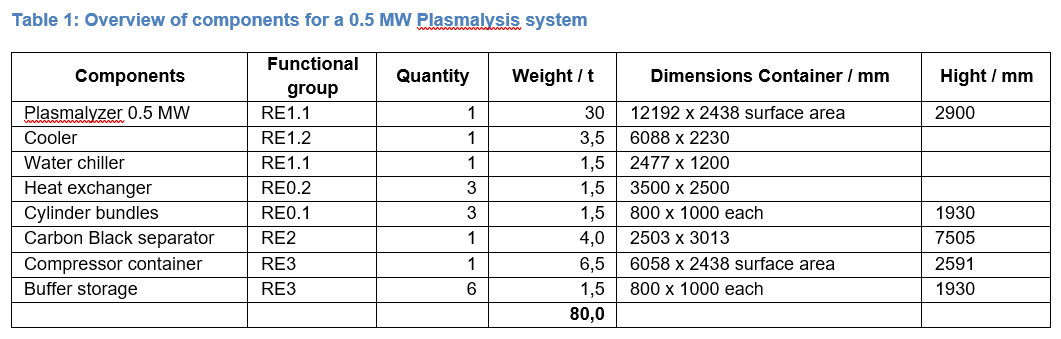
Q 1.2 What plant components does the Methane-Plasmalyzer (0.5 MW) consist of?
The Graforce Plasmalyzer plant is a modular system solution with a production capacity of 50 kg H2/h and approx. 150 kg Carbon/h, consisting of five functional units:
The overall plant is divided into operational units for better description. The division of the plant into operational units is presented in the process flow diagram below.
An operational unit refers to a process-related and/or operationally connected sub-unit of the overall plant, which can consist of systems, system components, auxiliary systems, or support facilities. An operational unit does not necessarily have to be structurally contiguous.
Operational Unit RE1: Methane-Plasmalysis System
Main components include:
- Methane-Plasmalysis systems, including power generators
- Heat exchanger system
- Process cooling
- Switchgear systems
- AC, DC, uninterrupted AC, standby, and emergency power supply
- Measurement, control, and regulation technology, including associated cabling
- Hydrogen venting lance for controlled and safe hydrogen release
Operational Unit RE2: Carbon Separator
Main components include:
- Carbon separator with polymer filter, and screw conveyor
- Switchgear systems
- AC, DC, uninterrupted AC, standby, and emergency power supply
- Measurement, control, and regulation technology, including associated cabling
Operational Unit RE3: Gas Compression and Low-Pressure Storage
Main components include:
- Low-pressure compressor for gas compression
- Buffer storage
- Auxiliary cooling water system and recooler
- Switchgear systems
- AC, DC, uninterrupted AC, standby, and emergency power supply
- Measurement, control, and regulation technology, including associated cabling
- Hydrogen venting lance for controlled and safe hydrogen release
Operational Unit RE4: Carbon Storage
Main components include:
- Container
- Carbon filter
- Loading fixture
- Carbon transport screw
- Measurement, control, and regulation technology, including associated cabling
Operational Unit RE5: Utility Site
Main components include:
- Power connection
- Transfer point for natural gas extraction
Additional Systems:
Control System – Mainly consisting of:
- Supervisory computers (servers)
- Bus systems
Control and monitoring interface
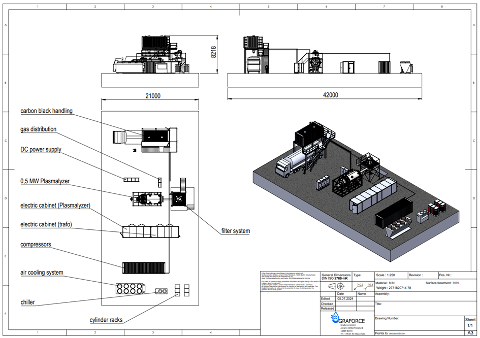
Q 1.3 What does the plant installation look like and what are unit dimensions and weights?
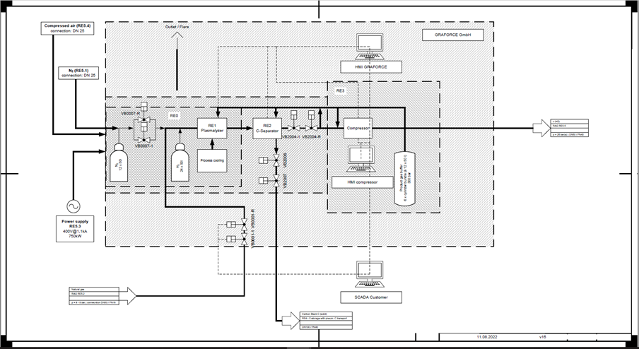
Q 1.4 What does the PFD for this plant solution look like?
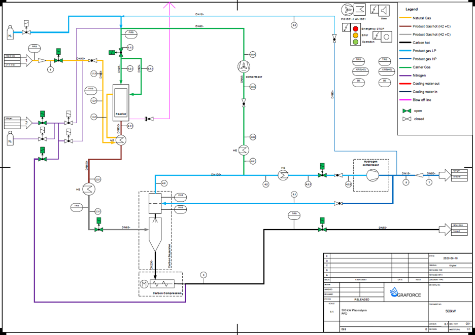
Figure 4 shows the PFD for a 0.5 MW Plasmalyzer consisting of one plasma reactor, a carbon separation and compression unit, several heat exchangers for hot water generation and a compressor to deliver the required pressure of the product gas. The yellow line is the feed gas which is injected into the plasma reactor chamber, brown the raw product gas (hydrogen with carbon black), black the separated and compressed carbon black and blue the hydrogen product. The green line shows the so-called sweep gas, which is the partially recirculated hydrogen product stream and serves as the carrier gas for the plasma.
Q 1.5 What is the delivery pressure of hydrogen and what does the compressor container (RE3) consist of?
The delivery pressure of the hydrogen product always depends on the downstream aggregates. For hydrogen as fuel in H2-CHP units or H2-turbines a pressure of 5 – 20 bar is required. A 360 kWel H2-CHP needs an inlet pressure of 5 – 10 bar while a 1 MW H2-CHP needs an inlet pressure of 15 – 20 bar. A 2 MW hydrogen turbine requires an inlet pressure of about 20 bar.
For H2-compression a 2-stage compressor can be used. This would be powered by a 45 kW electric motor with 2 pistons per stage and a compression capacity of 0.3 barg to 25 barg with a throughput of 600 Nm³H2/h. The compressors are mounted on a base frame with a sump.
The container is equipped with sound baffles for ventilation. Gas detectors for methane and hydrogen are installed in the container, which in case of response cause an immediate alarm and shutdown of the entire unit.
Q 2.1 What are the requirements for the ground?
The floor plan of the plant provides for a level, load-bearing base of at least 17 m x 15 m (for a 0.5 MW Methane-Plasmalysis system). Heat exchangers, carbon separators, cylinder bundles, etc. are positioned between the containers. The area for carbon handling will be separate and is not included here.
Q 2.2 What equipment and operating material is required?
Following equipment and operating materials are required:
- Natural gas supply
- Nitrogen supply
- Nitrogen emergency supply via cylinder bundles
- Control air supply
- Power supply
- Chiller (necessity depends on the heating concept)
For inerting of plant sections in the respective operating modes, nitrogen must be provided from a nitrogen generation plant for the Methane-Plasmalysis plant. In order to be able to ensure inerting even in the event of failure of the nitrogen generation plant, additional nitrogen bundles with 12 x 50 l at 200 bar must be provided.
A separate system with compressor, dryer and compressed air tank is required for the control air supply. The operating pressure of this system is a maximum of 7.5 bar(g) and a maximum volume flow of 1.8 m³/min.
The power supply for the power section of the RE1 is provided directly from the low-voltage main distribution of the transformer station via four independent circuit breakers. These are equipped with undervoltage releases and integrated into the emergency stop chain.
Q 3.1 Wich feedstock is used ?
In the Plasmalyzer, methane from natural gas is dissociated into hydrogen and carbon using high-voltage plasma. The system can handle a wide range of methane concentrations and is capable of processing various hydrocarbon compounds up to C₆.
While the process is optimized for feed gases with ≥ 98 vol.% methane, natural gas with lower methane content can also be treated effectively. In such cases, the higher proportion of inert or reactive components may require additional downstream purification, depending on the desired hydrogen purity and final application.
Impurities such as nitrogen, carbon dioxide, carbon monoxide, or higher hydrocarbons (e.g., ethane, propane, butane) do not interfere with the plasma process itself but can influence the product gas quality. For instance, carbon dioxide can react with methane to form hydrogen and carbon monoxide, while nitrogen remains inert and unconverted in the system.
Biogas produced by fermentation of biomass is generally burned in combined heat and power (CHP) plants and used to generate electricity. In order to take a consistent step towards a circular economy and possibly even create a CO2 sink, biogas or biomethane can be converted into green hydrogen and carbon using the process of Methane-Plasmalysis. The energy required for this can be obtained, for example, by solar collectors and the conversion of biogas into electricity. The basic material for bioMethane-Plasmalysis is biogas, which is upgraded by amine scrubbing, for example, to obtain biomethane as feedstock. In a plasma field, biomethane is then split into its components hydrogen (H2) and carbon (C). The hydrogen can be used directly for carbon free heat and power generation or further purified in order to be used as fuel for example. Carbon Black could be applied in tires, rubber, paints and varnishes, in asphalt or for soil improvement. Long-term storage in product for example of solid carbon enables long-term removal of CO2 from the cycle and can create a carbon sink.
Flare gas is a special case because it has high concentrations of other hydrocarbons, CO2 and nitrogen. Higher levels of other gases can affect the operation of the plasma. Therefore, additional purification (e.g. by membrane technology) of the partial recirculation stream from the product gas serving as carrier gas for the Plasmalysis process, is required. For other hydrocarbons than methane (CxHy with x>1), the mass ratio m(C)/m(gas) is always greater than for CH4. The mass fraction of hydrogen on the other hand decreases in relation to the molecular mass, meaning higher-value hydrocarbons (CxHy with x>1) also release more carbon.
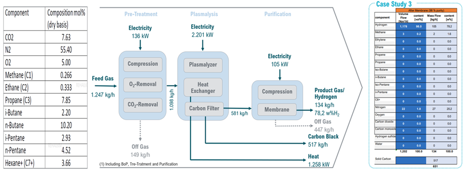
The diagram illustrates a process chain for plasma-assisted hydrogen and carbon production from a complex hydrocarbon-rich waste gas stream with a high inert gas content. The feed gas amounts to 1,247 kg/h and consists primarily of nitrogen (55.4 mol%), oxygen (5.0 mol%), and heavier hydrocarbons—most notably n-butane (10.2 mol%), n-pentane (4.5 mol%), and C7+ fractions (3.7 mol%). Methane is present at only 0.27 mol%, indicating that the input is not conventional natural gas but rather a process or flare gas.
In the first stage (pre-treatment), oxygen and CO₂ are removed, reducing the mass flow to 1,098 kg/h, with about 149 kg/h of off-gas separated. The core of the process is the plasmolysis step, where the gas mixture is physically dissociated into hydrogen and solid carbon under high temperatures, powered by a plasma input of 2,201 kW. Solid carbon is separated via a filter, yielding 517 kg/h, while 1,258 kW of recoverable heat is also generated and can be used for downstream industrial applications.
The gaseous product is then compressed and purified via a membrane separation unit. This produces 134 kg/h of product gas with a hydrogen content of 78.2 wt% (corresponding to approximately 105 kg/h of pure hydrogen), while 447 kg/h of off-gas—mainly nitrogen, CO₂, and residual hydrocarbons—is discharged.
This case study demonstrates the system’s capability to convert methane-poor, nitrogen-rich hydrocarbon gas streams into valuable hydrogen and solid carbon products, with a total electrical energy input of approximately 2.4 MW. The high carbon and heat yields, along with clean hydrogen output, offer a versatile and efficient decarbonization pathway for industrial sectors.
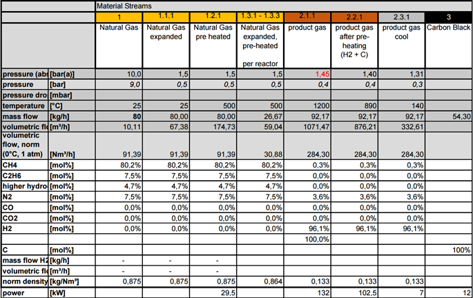
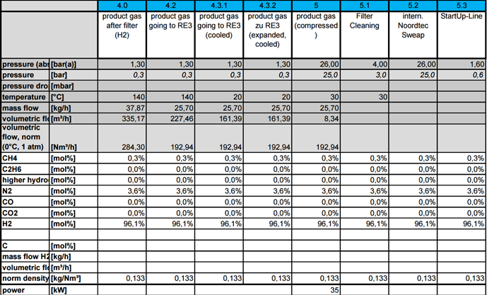
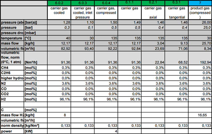
The next application described here uses a 0.2 MW Plasmalysis module specifically designed to process a flare gas mixture composed of approximately 80.3 mol% methane, with additional components including ethane (7.5 mol%), propane (2.9 mol%), and nitrogen (7.5 mol%). Trace components such as CO₂ (3.2 ppm) and H₂S (0.46 ppm) are negligible. In the process, the input gas is first preheated to 500 °C and then fed into a plasma reactor, where it is exposed to a high-temperature hydrogen plasma, generated by a DC-powered plasma torch operating at temperatures exceeding 1500 °C. Under these conditions (see Table 3: Mass-Energy-Balance with a 200kW module), the methane molecules dissociate into their elemental components: molecular hydrogen (H₂) and solid carbon (C). The reaction takes place under near-atmospheric pressure and in the absence of oxygen. The process results show that from approximately 80 kg/h of input gas, around 92 kg/h of product gas (feed + carrier gas) is generated, with a hydrogen concentration of about 96.1 mol%. The remaining components consist mainly of nitrogen (3.6 mol%) and residual methane (0.3 mol%). Simultaneously, about 54.3 kg/h of solid carbon is produced in the form of high-purity carbon black.
Table 3: Mass-Energy-Balance with a 200kW module
Q 3.2 Can methane plasmalysis also produce syngas, and what does a techno-economic analysis look like for a 20 MW plant with 40 modules?
With natural gas, biomethane, LNG, LPG or flare gas as feedstock for our Methane Plasmalyzer, main output products are hydrogen and solid carbon. The same system allows the use of biogas (CH4 + CO2) as feedstock though which results in the production of syngas consisting of hydrogen and carbon monoxide. Syngas is an important basic material for the chemical industry and serves as a feedstock for the production of synthetic fuels such as gasoline and kerosene.
Tests with different biogas ratios as feedstock for our Plasmalyzer have been carried out. At a biogas ratio of 50 % CH4 and 50 % CO2 a product gas ratio of H2:CO = 1:14 was generated. The required energy input was approx. 26 kW/kgH2. The chemical equation is as follows:
CH4 + CO2 -> 2 H2 + 2 CO
With higher methane concentrations and an input gas ratio of CH4:CO2 = 2:1 the chemical equation changes to:
2 CH4 + CO2 -> 4 H2 + 2 CO + C
Here, the stoichiometric ratio is 2:1 for both the raw biogas and the product gas, producing more hydrogen and solid carbon. With this biogas composition a product gas ratio of H2:CO = 1:7 was generated. The required carbon separator would be about half the size of the classical Methane-Plasmalysis with the same gas volume.
Our Plasmalysis process is electricity-based, CO₂-negative or CO₂-neutral alternative for syngas production that can economically replace SMR and gasification.
Our technology is well-suited for exactly this purpose:
- Direct Plasmalysis of CH₄ + CO₂ produces syngas with an adjustable H₂/CO ratio
- No external heat or fossil energy required – fully electrically powered
- No CO₂ emissions, instead active CO₂ utilization
- Optional addition of CH₄ Plasmalysis allows targeted adjustment of the H₂/CO ratio
- POX (O₂ addition) is technically feasible but has not been implemented for safety reasons – alternative configurations are possible
We have prepared a techno-economic analysis (TEA) focusing on synthesis gas production. The TEA for the 20 MW plant can be found on our website under Syngas and consists of.
- The system consists of 30 syngas modules (12 kWh/kg H₂) and 10 hydrogen modules (8 kWh/kg H₂), optimized through full utilization of high-temperature waste heat (module outlet temperature: 1200 °C). Electricity is provided on your side at €0.07/kWh, assuming 8400 operating hours per year and no PV integration. CO₂ is internally captured from refinery off-gases at no cost (€0/kg), and the analysis assumes 100% co-valuation of solid carbon at €500/t. Hydrogen sales are calculated at €2/kg, with CO priced in the range of €0.20 to €0.50/kg.
- The updated TEA confirms that our plasma-based solution can serve as a direct and competitive alternative to SMR and gasification – both technically and economically. Levelized cost of syngas (LCOSyngas) is calculated at €0.23–0.38/kg, which is already within a commercially viable range. Beyond that, the process is fully electric and CO₂-neutral to negative. Approximately 3213 Nm³/h of CO₂ is utilized from the refinery, and around 70% of the methane carbon is permanently sequestered as solid carbon (12600 t/year).
- In terms of energy consumption, the weighted average across both module types is around 5–11.5 kWh/kg H₂ – just slightly above your target threshold of 10 kWh/kg. However, this is economically offset by the co-valorization of carbon and the use of process waste heat, which fully covers internal heating demands and also generates additional value. Depending on CO pricing, profit margins reach up to €0.43/kg syngas, with a total annual profit potential of €33 million. Payback time is between 1.5 and 2.5 years, and the internal rate of return (IRR) can reach up to 50 %.
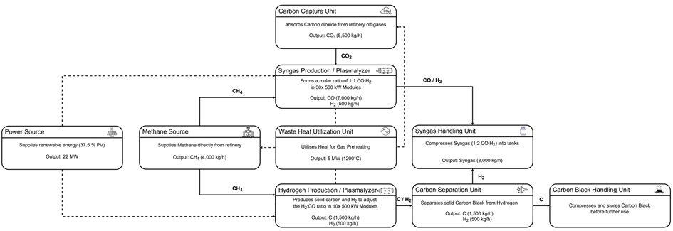
Figure 11: Block diagram for syngas production with 2:1 H₂:CO ratio
4. Plasma-Process
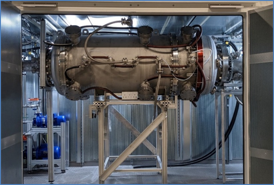
Q 4.1 What does the plasma reactor look like and what materials are used?
The plasmalysis module consists of an outer casing containing the reactor core. The casing of the module is made of stainless steel (Material No. 1.4541) while the plasma chamber (module core) is made of graphite. The reactor chamber is assembled, equipped with a magnetic coil for gas flow guidance and mounted into the casing. The figure show the 200kW module.
Plasma Generation:
- Plasma Source: Plasma is created using two graphite electrodes in the plasma chamber. The feedstock used for the plasma is recycled hydrogen.
Feedstock and Temperature:
- Feedstock: Methane, natural or flare gas is dissociated into hydrogen and solid carbon through heat and plasma electrochemical processes in the graphite chamber.
- Temperature: The chamber operates at temperatures between 1500 °C and 1600 °C.
Process Conditions:
- Conversion Efficiency: Approximately 98% of methane is converted within a short residence time of 200 ms to 500 ms.
- Waste Heat Utilization: The generated high-temperature waste heat (1200 °C) can be used for additional processes, such as steam or hot water production. 25% of the generated high-temperature waste heat is reused to preheat the feed gases (methane and recycled hydrogen), enhancing the overall energy efficiency of the process.
Q 4.1.1 What does the electrode look like and how does the electrode exchange system work?
High local temperatures in the plasma reactor cause the middle electrode to be slowly “consumed”. This means that a regular replacement of the electrodes is necessary. The consumption of the middle electrode is about 0.22 g/kWh, depending on intensity of the magnetic field. You can choose between two electrode feed systems. The single feed unit system has one electrode that is automatically tracked and has an operating time of 100 hours. Once the electrode has been used up, the plasma must be switched off and the electrode chamber must be inerted with nitrogen. A new electrode can then be inserted into the electrode system and the plasma process restarted. The single electrode feed unit is included in the standard scope of the Methane-Plasmalysis system.
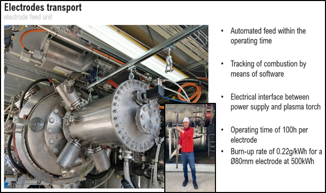
The automatic electrode exchange system fits 18 electrodes. The total cost per year for the exchangeable electrodes is approx. 12.000 € per year (with 8.000 h). Refilling the electrodes does not require the plasma system to be inertized. However, the plasma must be stopped briefly. Only then can the system be refilled with new electrodes. An electrode cassette system enables continuous operation, but its acquisition cost is three times higher than that of the single-electrode system.
Q 4.2 What is the carrier gas for the plasma?
A partial stream of the generated hydrogen serves as carrier gas for the plasma reactor and is used to heat the reaction chamber. The mass flow of the carrier gas depends on the mode of operation of the system. Both hydrogen and methane are heated inside the graphite cores.
Q 4.3 What voltage and current of the DC plasma are currently applied?
The DC plasma system is ignited with an LF device and driven out in the electrode channel (at about 80 V and up to 30 A). After driving the plasma out of the electrode channel, the voltage increases up to 700 V (H2).
Q 4.4 What does the conversion rate of e.g. methane depend on?
The residence time of the feed gas, electrical power input and the temperature in the plasma reactor are the main factors influencing the conversion rate of e.g. methane (see Figure ).
Q 4.5 What is the energy demand for the entire Plasmalysis system?
The specific energy demand for the plasma reactor is approx. 11 kWh/kgH2 (Including heat recovery) and there is an additional energy demand for the separation and compression of carbon black, fittings and H2-blower of about 4 kWh/kgH2.
To calculate the electrical cost (EC), the power consumption of all electrical consumers is summed up and referenced to the produced hydrogen for comparability:
EC = Sum of all consumers per kg(H₂) [kWh/kg(H₂)]
Please see also Table 3: Energy balance of the 500kW Plasmalysis module with preheating
The largest consumer is the DC generators, followed by blowers, pumps, compressors, etc. All consumers are listed in the following table.
Table 4: Power consumption 0.5 MW Methane-Plasmalysis plant
|
No. |
Component |
Power (kW) |
|
1 |
Plasma Power |
500.00 kW |
|
2 |
Sweep Blower |
30.00 kW |
|
3 |
Axial Duct Fan 1 Container 2 |
0.30 kW |
|
4 |
Axial Duct Fan 2 Container 2 |
0.30 kW |
|
5 |
Axial Duct Fan 1 Container 2 |
0.30 kW |
|
6 |
Axial Duct Fan 2 Container 2 |
0.30 kW |
|
7 |
Membrane Gas Pump (behind gas sensor) |
0.20 kW |
|
8 |
Screw Conveyor |
8.05 kW |
|
9 |
Space Heater 1 – Machine Room Container |
1.50 kW |
|
10 |
Space Heater 2 – Machine Room Container |
1.50 kW |
|
13 |
Circulation Pump Heating Circuit 1 |
7.50 kW |
|
14 |
Circulation Pump Heating Circuit 2 |
3.00 kW |
|
15 |
Circulation Pump Heating Circuit 3 |
3.00 kW |
|
16 |
Circulation Pump Heating Circuit 4 |
15.00 kW |
|
17 |
Circulation Pump Heating Circuit 5 |
1.40 kW |
|
18 |
Split Air Conditioning Unit 1 |
1.85 kW |
|
20 |
Free Cooler |
21.88 kW |
|
21 |
Chiller |
33.90 kW |
|
Subtotal Graforce |
629.38 kW |
|
|
22 |
Compressor 25bar |
90.00 kW |
|
23 |
Carbon handling system |
20.00 kW |
|
Total Power Consumption |
739.38 kW |
If only the total power consumption of 764 kW is considered for approx. 50 kg(H₂)/h.- 15.28kWh with periphery (compressor & carbon handling). By preheating the gas flows (natural gas feed and hydrogen sweep) using the hot product gas to 500°C and 700°C, respectively, the EC can be reduced.
- In the first heat exchanger, 136 kW of energy is transferred from the product stream to the sweep gas, heating it to 700°C.
- In the second step, the natural gas is preheated to 500°C, transferring 83 kW from the product gas to the natural gas feed.
The preheating of natural gas is limited by the onset of pyrolysis, which begins at around 700°C. If pyrolysis occurs within the piping, it could lead to clogging due to carbon deposition.
Advantages of Gas Stream Preheating
- Utilization of process heat, increasing process efficiency.
- Higher reactor inlet temperature (~1500°C), leading to higher methane conversion (~98%), which improves hydrogen production.
By utilizing process heat, the EC is reduced from 15.3 kWh/kg(H₂) to 11.0 kWh/kg(H₂).
Depending on the required hydrogen quality and pressure, an additional gas purification process and compressor station might be necessary. In order to provide 5.0 hydrogen, e.g. a pressure swing adsorption (PSA) system would be required downstream the Plasmalyzer. The energy demand for this additional step and also for the hydrogen compression to e.g. 300 bar is not included in the mentioned energy demand for the Methane-Plasmalysis system.
Q 4.6 Are there any limiting factors e.g. min/max feedstock flow rates, temperature, pressure etc.?
The plasma process operates at slight overpressure (max. 1.5 bara). The minimum gas velocity has to be above 18 m/s in order to prevent carbon deposition in the aggregates. Exceeding the maximum flow rate leads to a shorter residence time of the gas in the plasma chambers and thus to a lower conversion rate.
Q 4.7 Are there any limiting factors e.g. min/max feedstock flow rates, temperature, pressure etc.?
The plasma process operates at slight overpressure (max. 1.5 bara). The minimum gas velocity has to be above 18 m/s in order to prevent carbon deposition in the aggregates. Exceeding the maximum flow rate leads to a shorter residence time of the gas in the plasma chambers and thus to a lower conversion rate.
Q 4.8 What are the unique features of Graforce’s plasma technology?
|
Criterion |
Graforce |
Competitors |
|
Reactor Design |
Fully graphite-based, no active cooling required, no catalyst needed |
Metallic reactors, often require active cooling, material-intensive, catalyst clogging due to carbon |
|
Plasma Generator / Energy Source |
Efficient DC plasma source with >95% electrical efficiency |
Often microwave or RF plasma with low wall-plug efficiency (55–70%) |
|
Electrode Material / Wear |
Graphite, very low wear, durable, automatic feed system |
Metal electrodes, high wear, require cooling and frequent replacement |
|
Electrode Replacement |
Automated replacement system, <2 min downtime |
Manual or not feasible, leads to extended downtimes |
|
Maintenance Interval |
Up to 6 months (with automated heat exchanger cleaning) |
Often just weeks to a few months |
|
Energy Demand (incl. peripherals) |
15 kWh/kg H₂ (proven in continuous operation) |
20–40 kWh/kg H₂ (without peripherals), mostly theoretical values |
|
CH₄ Conversion Rate |
Up to 98% (only 2% residual methane, no other gases that are hard to separate) |
Typically 80–90%, often lower |
|
Partial Load Capability |
Fully partial-load capable, rapid load changes via H₂ recirculation |
Rarely possible, mostly designed for full-load operation |
|
Scalability |
0.5 MW modules, linearly scalable, maintenance-friendly |
Large-scale reactors, complex maintenance, not partial-load capable |
|
Fouling Risk |
Low thanks to controlled gas flow, compact reactor volume, and modular design |
High in large reactors, uneven temperature distribution and carbon quality issues |
|
Product Diversity |
H₂, solid carbon, high-temperature waste heat, optional syngas |
Mostly H₂ or syngas, by-products not utilized |
|
Carbon Quality & Utilization |
Precisely controllable (even graphitic), proven industrial usability |
Mixture of amorphous/nano/graphitic forms, hard to monetize |
|
Carbon Offtake & Market |
Substitute for petcoke in TiO₂, electrodes, cement, steel, soil, batteries, etc. |
Often no defined offtake, unclear monetization pathway |
|
Certifiability |
PFAS-free, membrane-free, LCDA-compliant |
Complex materials, challenging certification |
|
Feedstock Flexibility |
NG, biogas, flare gas, CO₂ → syngas (proven) |
Often methane only, no demonstration of CO₂ or flare gas usage |
|
Decarbonization Potential |
CO₂-free process with storable solid carbon (certifiable as CDR) |
Partial CCS, not CO₂-free due to tailgas and low conversion |
|
Technology Readiness Level (TRL) |
TRL 7, continuous operation at industrial partner site |
Mostly lab-scale, limited pilot data |
Graforce has developed a unique plasmalysis technology that produces hydrogen from fossil or biogenic hydrocarbons such as natural gas, biogas, or flare gas without CO₂ emissions—with exceptionally high efficiency, scalability, and product quality.
At the heart of the system is a fully graphite-based plasma reactor that does not require active cooling, offering significant advantages in terms of energy consumption and maintenance. Particularly noteworthy is the very low wear on the inner electrode – a decisive factor for low OPEX and high plant availability.
The patented electrode tracking and replacement system allows for fast maintenance cycles with minimal downtime. Combined with a high CH₄ conversion rate of up to 98% and a system energy requirement of only 15 kWh/kg H₂ (including peripherals), Graforce is one of the most efficient technologies worldwide. In addition, the integrated H₂ recirculation system enables fully partial-load operation with rapid load adjustment, making it particularly attractive for use in dynamic energy systems and industrial processes.
Scaling is achieved using standardized 0.5 MW modules, which are delivered preconfigured and connected in parallel. This modular concept lowers the plant risk, reduces fouling effects, and ensures consistently high carbon quality, even when individual modules are being maintained. Automated cleaning of the heat exchangers allows maintenance intervals of up to 6 months to be achieved – a significant advantage over conventional thermal processes.
In terms of materials, the system is membrane-free, PFAS-free and contains no rare metals, which not only increases its environmental compatibility but also significantly facilitates certification under European and international regulations (e.g., LCDA).
Graforce not only supplies green and low-carbon hydrogen, but also produces high-purity solid carbon, the quality of which can be controlled to graphite-like levels, depending on the process control. This flexibility is technologically unique and has already been analytically proven.
In addition, there are concrete industrial cooperation partnerships with customers who use Graforce carbon as a substitute for climate-damaging petcoke – for example, in titanium dioxide production, steel and bitumen modification, battery technology, the cement industry, and agriculture. Long-term storage as a soil improver for more than 400 years has been successfully tested and offers additional potential for certification as a carbon removal technology. The addressable market for high-purity carbon is in the billions and is strongly favored by regulatory drivers such as ETS2 and CRCF.
In addition, the processing of flare gas has been demonstrated, as has the production of syngas (e.g., for Fischer-Tropsch processes). Integration into H₂ CHP and H₂ turbine plants is being prepared with partners and significantly expands the range of applications for decentralized energy systems.
Q 4.9 Cost Summary QMRO and maintenance cycle for 0.5 MW Plasmalysis plant
The annual operating and maintenance costs (QMRO) for a 0.5 MW plasmalysis plant operating between 8,000 and 8,400 hours per year (depending on the feed gas) amount to approximately €37,300. The costs break down as follows: Semi-annual maintenance by two technicians, blower servicing, and calibration of safety- and process-critical sensors total around €11,700 per year. Annually replaced wear parts such as seals, hoses, and insulation cost approximately €10,000. Electrodes in the plasma reactor account for annual costs of about €12,000. The carbon filter unit, with a service life of around 44,000 hours, contributes proportionally about €3,600 per year.
This corresponds to a typical maintenance ratio of approximately 2% of capital expenditure (CAPEX).
Q 4.10 Can you start with one 0.5 MW module and scale up later?
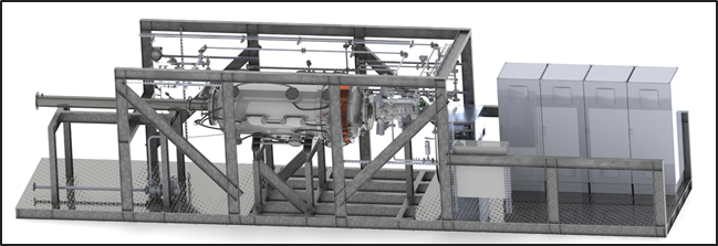
Yes, the Graforce Plasmalyzer® is based on a modular design, allowing you to start with a single 0.5 MW module and scale up gradually over time. Each module is pre-assembled on a standardized skid that includes all key components – reactor, heat exchanger, gas flow system, measurement and control units, power supply, and hydrogen/carbon separation systems. This setup enables quick on-site installation with only minimal connection work required for electricity, gas, and optional heating or cooling lines.
Scaling up is straightforward: additional modules are simply connected in parallel. For example, a 10 MW plant can be built by combining 20 modules, while a 20 MW plant uses 40 modules and can produce around two tonnes of hydrogen per hour. The modules operate largely independently and can be turned on or off individually, allowing for maintenance during ongoing operations and flexible adaptation to fluctuating electricity availability—particularly relevant for renewable energy integration.
This modular approach offers significant economic and operational advantages. It enables a low-risk market entry with smaller initial investments and allows for demand-based expansion tailored to the specific conditions of each site. Redundancy across modules also increases system reliability: if one unit is offline, the others continue to operate. The modular scalability of the Plasmalyzer® thus makes it well-suited for both large-scale industrial applications and decentralized deployment.
Q 4.11 Which Industries Need Low-Carbon Hydrogen and Solid Carbon?
Industrial Heat and Process Applications
- Cement Industry – for preheaters and calcination units
- Glass Industry – for melting furnaces and float glass processes
- Steel Industry – for reheating furnaces and drying applications
- Ceramics & Refractory Materials – for high-temperature kiln processes
- Drying & Thermochemical Processes – e.g. biomass treatment, textile, paper
- Absorption Cooling / Sorption Heat Transfer – using industrial waste heat (e.g. data centers)
- District Heating Integration – for high-temperature industrial heat networks
Carbon-Based Material Substitution and Functional Uses
- Pigment and Colorant Industry – e.g. as carbon black substitute in TiO₂ production
- Battery and Electronics Industry – as conductive additive or carbon carrier in Li-ion and sodium batteries
- Metallurgy and Steel Refinement – as recarburizer for melt adjustment
- Electrode Manufacturers (Graphitization) – for EAF and aluminum smelting electrodes
- Bitumen and Asphalt Industry – to improve performance (e.g. frost and heat resistance)
- Soil Enhancement / Carbon Farming – as permanent carbon sink in volcanic soils or dryland reclamation
- Filtration and Adsorption Materials – e.g. for water treatment (PFAS, heavy metals, microplastics)
Chemical and Energy Systems
- Synthetic Fuels (e-Fuels, PtL) – via Fischer–Tropsch or methanol synthesis
- Methanation (Sabatier Reaction) – for CO₂ recycling in closed-loop systems
- Reforming / Steam Gasification – e.g. for ammonia synthesis or methanol cycles
- Refinery and Petrochemical Circular Processes – to reduce fossil cracker gas or flare gas
- Digital and Decentralized Infrastructure
- Data Centers & Critical Infrastructure – as low-emission fuel for SOFC baseload and backup power, with added value through high-temperature heat recovery (e.g. for heating or absorption cooling – fuel flexibility: CH₄, H₂, CO)